Relations
General
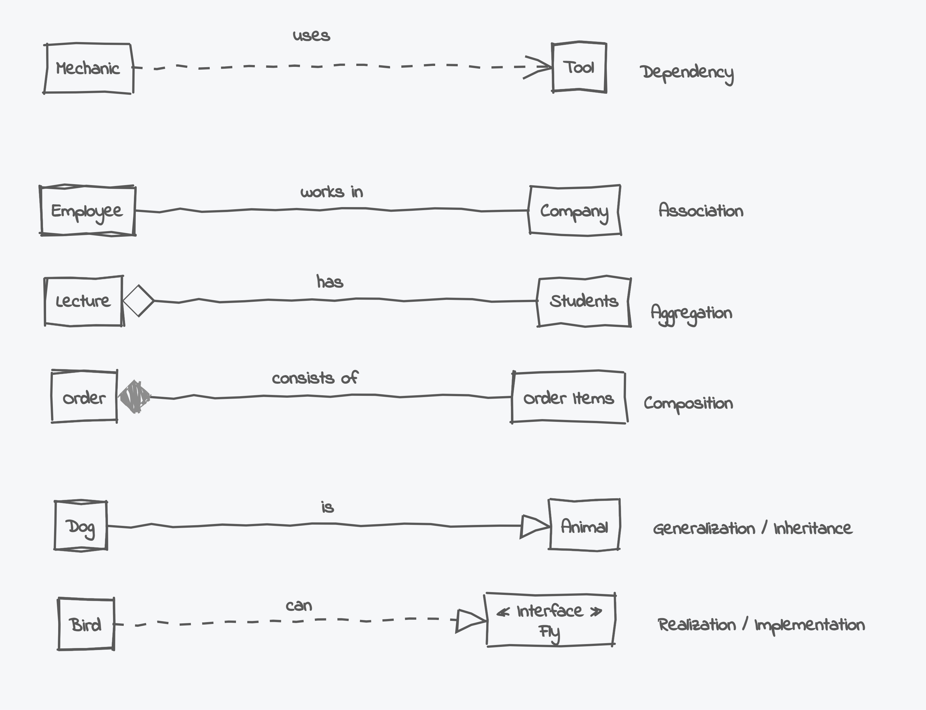
Relations in UML class diagrams are a way to express whether and how two classes are connected. UML supports six different types of relations: Dependency, Association (which can be further specified as Aggregation or Composition) and Generalization and Realization.
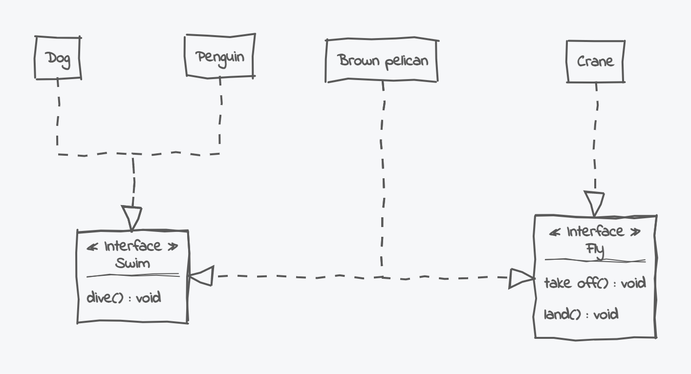
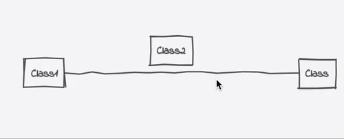
Deciding which relation is best used to model a specific connection is not always easy. The following diagram shows examples for all six relations. Still, whether these connections make sense may depend on the concrete scenario or the domain you want to model.
See the following diagram for some examples:
We will now investigate the different types in more detail.
Dependency
Dependency is the weakest type of relation in UML class diagrams. It is considered weak because the relationship between the two ends (the source and the target class) is only temporary or restricted to a single method or constructor.
To draw a dependency, use a dotted line and an open arrowhead pointing to the target class. See the following diagram as an example of a dependency.
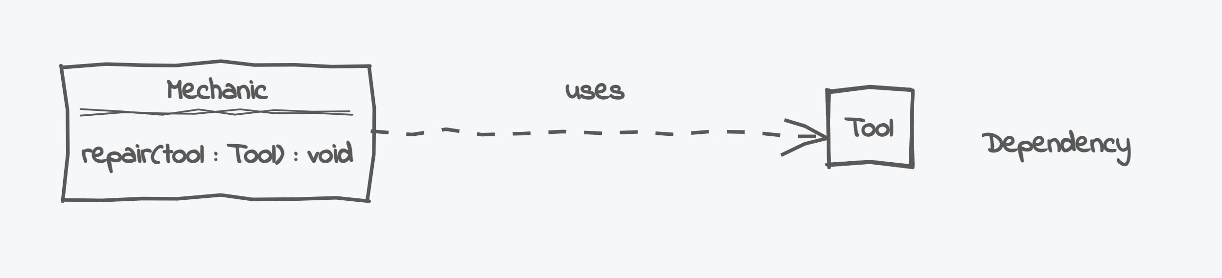
Our Mechanic class (the source) has a repair method that requires a specific Tool (the target), thus the method parameter tool creates a dependency between the two classes.
However, the dependency between the two types is not very strong as its only limited to this single method.
All other parts of the Mechanic do not depend on it.
When writing code, a dependency relation is often implemented as a method- or constructor parameter, or a method's return type. Our example from above could be implemented in the following way:
Dependencies have the advantage that they create only loose coupling. In the ideal case, you must only alter the methods that use the target class to remove a dependency, making refactorings relatively easy.
Association
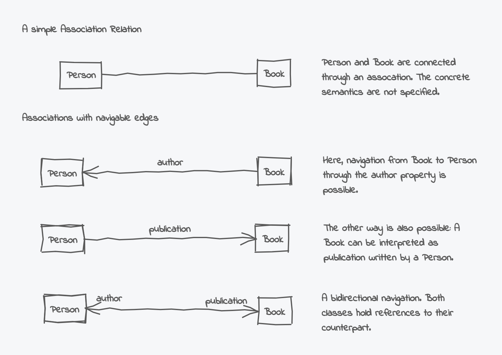
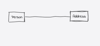
UML provides the concept of Associations to express more persistent and structurally stronger relationships than Dependencies. An association can, for instance, be used to model that one class holds a reference to another, e.g., through a property or a field.
In its simplest form, associations are drawn as simple, solid lines between their edges. Optional arrowheads can be used to specify whether navigation from one edge to the other (and vice versa) is possible.
According to the UML 2.0 specification, associations can further be differentiated into Aggregations and Compositions.
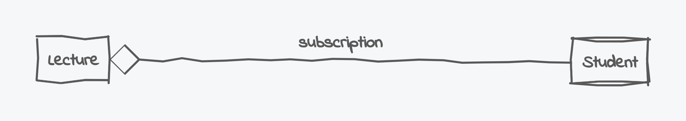
Aggregations should be used when one association class holds only a shared reference of the other, i.e., both types are connected, but their lifetimes do not depend on each other. Consider, for instance, the relation between a lecture and a student. The lecture references several students (e.g., through a subscription). However, it does not own these students. A single student could participate in several courses at once, and even if one of these lectures gets canceled, the student remains a student.
To draw an association in a UML diagram, use a hollow diamond at the source end of the relation (the one with the property referencing the other type).
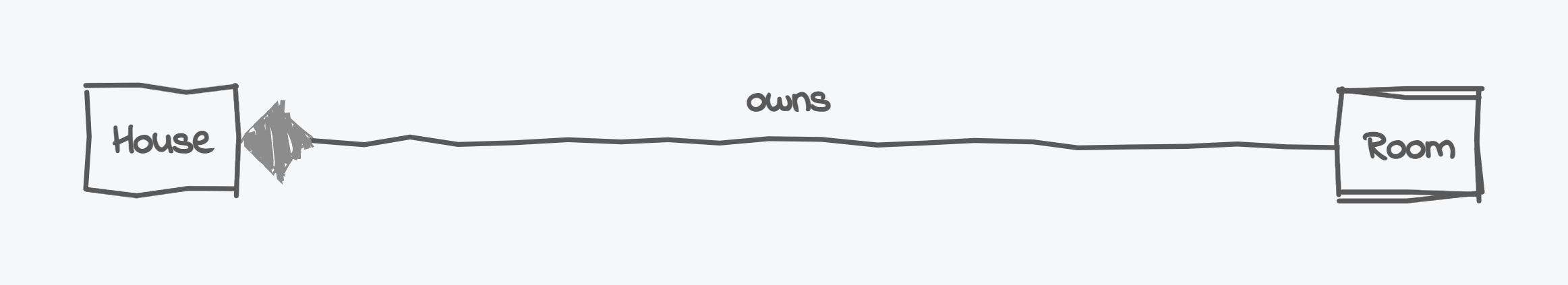
Compositions represent a much stronger parent-child hierarchical relationship. They are best used when the class holding the reference owns the referenced object and controls its lifetime.
Consider a house consisting of several rooms. A single room does not exist in isolation. Instead, it is very tightly coupled to its surrounding building. If you tear down the house, its rooms will be dissolved accordingly.
Usually, composition relationships are exclusive. Having two compositions pointing to the same reference doesn't make sense for most scenarios: A single room belongs to precisely one house - sharing it between several buildings would be a somewhat unintuitive conceptual decision.
Modeling compositions in UML is similar to aggregations. Draw a solid line between both types, but use a solid diamond on the source side this time.
When to use which type of association?
The choice between aggregation and composition depends on your use case.
Take, for instance, a simple racing video game where a Car class has several Tire references. The tires will likely be a fixed part of the car, and a single tire will not appear outside its containing vehicle. Therefore, a composition relation between the car and the tires would be reasonable.
Conversely, if you design a resource management system for a car reseller, tires would most likely be a concept of their own, and storing them without a corresponding car may be a very valid requirement. Here, aggregation would work better to connect a vehicle with its tires.
If unsure about your object's ownership and lifetime, you can also resort to the general association relationship. In this case, you are communicating that object ownership is not (yet) a primary concern of your concept.
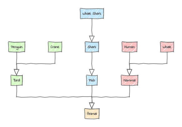
Generalization / Inheritance
While associations refer to a has a relationship, a generalization expresses a much stronger, is a relation.
Generalizations are used to express that one class is a more specialized version of another class. A dog, for instance, is a more specialized type of animal: It has all the behaviors and attributes an animal has. Still, on top of that, it adds some dog-like specific behavior.
Has a-relationships can be very dynamic - the instances on each edge can be changed anytime during runtime and even set to null. Generalizations, however, once defined, will remain over your application's whole lifetime.
As the name implies, generalizations are drawn as a solid line with an arrowhead pointing from the specialized to the more generalized type (i.e., from dog to pet). In this context, the target class of the relation is also called the base- or superclass, whereas the source type is called the subclass or derived class (as it inherits all properties from its base class).
Realization / Implementation
While realizations may look similar to generalizations, their purpose is very different. When using generalizations, we aim to build an ontology and reuse code implemented in base classes. Instead, when we use a realization relationship, we define a contract with a public interface to which our related types must conform.
By programming against interfaces, our code becomes more flexible. As long as our implementation classes conform to the same interface, we can now easily switch between different implementations.
Relationships in UMLBoard
Creating and Editing
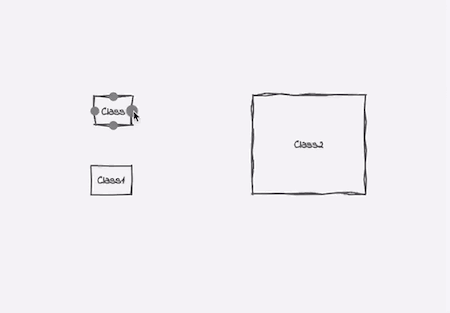
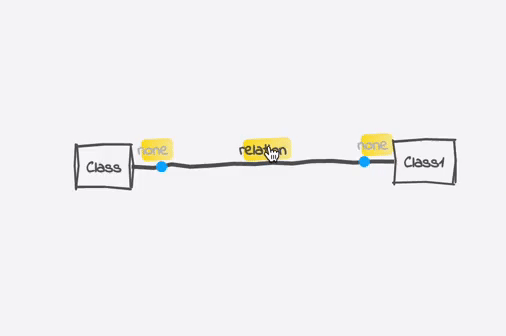
To create a relationship between two classes, start by dragging one of the connection points that appear when you hover the mouse over a class rectangle onto the target class.
After releasing the mouse on the target, a dialog with the list of available relationships should appear. The available options might vary depending on your source and target class type.
The created link will have a predefined description depending on the chosen relationship type. You can change it by long-pressing or double-clicking the text. Right-clicking on the connection opens a context menu with additional editing options: Switching the Connections allows you to
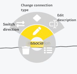
options for editing a connection.
UMLBoard will always draw an orthogonal connection path by choosing the least distant connection points as start and endpoints. The relation automatically updates if you move either the source or target element.
Connecting Notes
1.12 You can also draw a link from one note to another. However, connections between notes are just simple dashed lines that don't support any specific type.
Center Connection Point
1.12 Starting with UMLBoard Version 1.12, choosing one of the four connection points on the element's edges will lock this side and draw the connection always from this connection point. If you instead choose the connection point from the center of the element, the line will automatically choose the side that fits best for the starting point.
Anchor Points
1.6
The automatic routing algorithm should work for most basic scenarios but can be limited regarding more advanced layouts. To provide extra guidance to the automatic routing, you can add additional anchor points to a line by pressing Cmd / Ctrl + Click while clicking on a connection line. When drawing a connection between two elements (classes or notes), the algorithm will now always ensure that the line also goes through all anchor points associated with the relation line.
Just click and hold the mouse to drag the anchor point to a different position and see the changes applied to the routing instantly. In that way, you can force the connection to take a specific direction or move around elements.
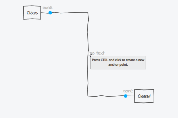
To delete an anchor point again, select it by clicking on it and press the Del or Backspace key.
Note
Anchor points don't change their position if you move the source/end of a relation separately (but do if you move both source and target simultaneously). Therefore, adjusting the anchor points might sometimes be necessary after moving one of the connection's elements.
Choose and Lock Docking Points
1.6
Using anchor points to customize the routing is suitable for more complex scenarios. Still, it can be a bit cumbersome for more straightforward designs. Here, it is often sufficient to define which sides of an element should be used for docking the connection line.
For this, you have two possibilities:
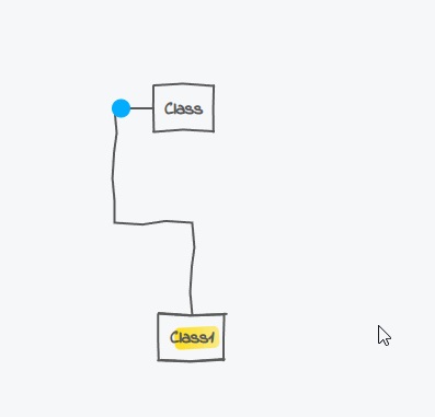
- For new lines: While drawing a new connection, just drag its end directly on the connection point of the target element you wish your line to connect to.
- For existing lines: Drag the connection's end marker (the blue dot at the end of a line) and drop it onto an arbitrary connection point. In that way, you can also change the source/target element of a connector after creating it.
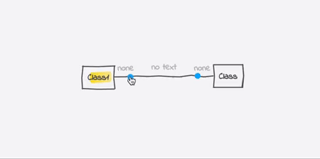
After that, the line's ending is locked to this specific point. The layout algorithm will no longer choose a different docking point, no matter where the source and target elements are placed. If you want to remove this constraint and enable auto-docking again, grab the line's end (the blue dot) and drop it directly over the element (and not over one of its docking points). The routing will then choose the docking point that guarantees the shortest connection between two elements.
Another way of locking/unlocking a line to a connection point is to right-click on the end indicator and choose the corresponding menu entry from the context menu.
Custom Docking Points
1.8
Suppose your class has many incoming or outgoing connections. In that case, only a single docking point for all links can impair the overview.
To dock your connection to an arbitrary point, press the Shift key while drawing the connection line over a class's border. A small dot will indicate the position of your new docking point. Release the mouse (while keeping Shift pressed) to create your connection.
Your new docking point will keep its position relative to the total length of the classifier's edge. So if you grow or shrink the classifier, the docking point will adjust its position according to the new size.
Tip
You can also use this approach when moving a connection's endpoint. Just press Shift and dock the endpoint at the desired position.
Associations and Properties
1.3
Whether you want to express a relation as an association or through an attribute is totally up to you. You can even start one way and later convert it to the other. For doing so, click on your property/relation and choose the corresponding menu element. You can, of course, undo or revert your decision any time by executing the contrary menu element.
properties and vice versa
Navigability
1.8
Navigability in UML describes how easy it is for a class instance to reach the object on the other side of a connection. If, for example, a connection has navigation arrows for both of its ends, that means there must be an efficient way during runtime to navigate from one edge to the other and vice versa (think, for example, of a double-linked list). How this navigation should actually be realized is implementation specific.
UMLBoard supports navigability for all types of associations and the usage relation. To set the navigation of a relation, you can pick the connection directly or choose one of its endpoints and select one of the Navigation context menu entries: Source, target, or both. Picking the same menu item again will remove the navigation from the corresponding edge.
Making the source of an aggregation/composition relation navigable does technically work. However, you won't see the resulting navigation arrowhead as it would overlap with the diamond symbol. Instead, you can draw two relations, one for the aggregation and the other for expressing the navigability from target to source.
Note
When loading diagrams created with a version older than 1.8.0, UMLBoard will automatically change the navigability of each usage relation to target to render the arrowhead correctly.
Moving Relations Vertically/Horizontally
1.9
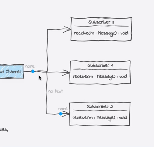
Sometimes, you want to draw several relations in parallel between two elements, e.g., when a class has more than one outgoing connection to another. So far, you have had to drag the endpoints of each relation separately to the desired positions. This can be cumbersome, especially if the space between your lines is small. Instead, you can now click on the relation's name and drag it up/down (or left/right) to move the whole connection to the desired position.
This works for all relations as long as they are orthogonally attached to their elements (either on two horizontal docking points or two vertical ones).
Tip
Instead of using the mouse, you can also use the arrow keys. Just click on the relation to select it and move the up/down or left/right keys to move the relation.
Moving a Relation's Name
1.9
While dragging a relation lets you change its position, pressing Shift while dragging its name allows you to move only the title while keeping the other parts untouched. This can be useful for long texts that would otherwise be overlapped by other diagram elements. The new text position will be "locked" and will have the following behavior:
- When moving both ends of the relationship, the text will keep its new place relative to both ends.
- Dragging only one end will not affect the text position. It stays "locked" at its current custom position.
You can always go back to the auto-positioning mode by right-clicking on the text and unchecking the lock menu entry. The layout algorithm will then calculate the new text position depending on the shape of the relation.
Choosing between Overlapping Lines
1.9
Ever had the problem that you could not grab a line because it was hidden by another one? Press Cmd (macOS) or Ctrl (Windows/Linux) and use the right/left arrow keys while hovering over the lines to step through them one by one. The currently top most line will be marked in bold color. After you reached the desired connection, click with the mouse to select it. Now you can easily manipulate the line.